Shape
Shape
Spline - Editing
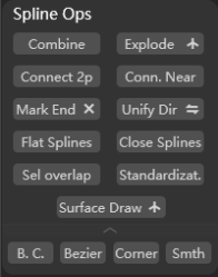
Supports quick and diverse editing of splines/shapes.
Combine: Click to combine selected splines and make a copy;Break Shap.: Break the shape and separate each segment of the spline;- Break
↑: Break the selected splines by endpoints; Connect 2p.: Click to connect 2 selected points;Conn.Near: Automatically identify nearby points to connectMark End: Mark and display non-closed endpoints;Unify Dir.: Unify the selected spline directions;- Unify Dir.
⇆: Reverse the direction of the selected spline; Flat Splines: Click to unify the Z axis of the selected spline;Close Splines: Close non-closed splinesPick Overlap: Pick out overlapping splines;Initialize: Initialize spline parameters;Surface Draw: Click to draw spline on the surface of objects;- Surface Draw
↑: Click to draw splines on the horizontal plane of the current perspective;
To further edit the vertex of selected spline, you may switch to edit mode and select the vertex, then:
B.Corner: Click to enable Bezier corner;B.Curve: Click to enable Bezier curve;B.Vertex: Click to enable Bezier vertex;Smoth.: Click to enable spline smooth;
Vertex - Optimize Vertex
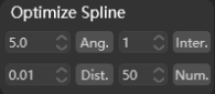
Support further editing of vertices on the selected spline. The units are based on the units in the current 3ds Max scene file.
Ang.: Edit and click to remove all vertex smaller than the set angle;Inter.: Edit and click to change the interval between each vertex;Dist.: Edit and click to remove all vertex within than the set distance;Num.: Edit and click to change the total number of vertex;
Step - Optimize
Supports Unify Steps according to the set parameters.
Double Spline

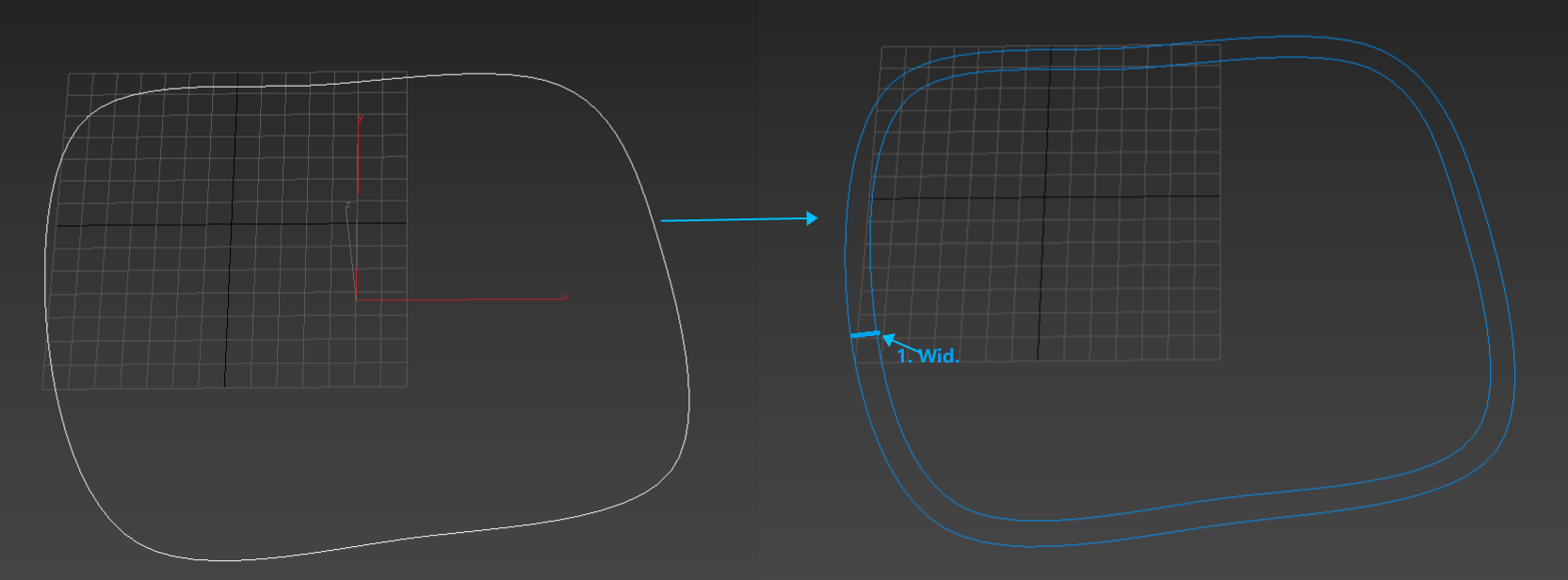
Support Convert the selected spline in double spline according to the set width (Wid.).
Shape – Precise Closure
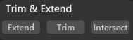
Supports trimming, extending and merging operations within one shape.
Extend: Select the target vertex and extend to end precisely within the shape;
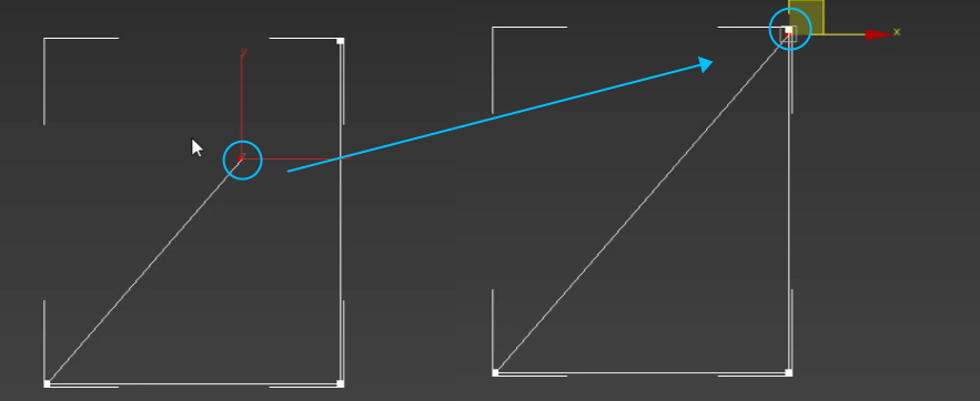
Trim: Select the target vertex and trim to end precisely within the shape;
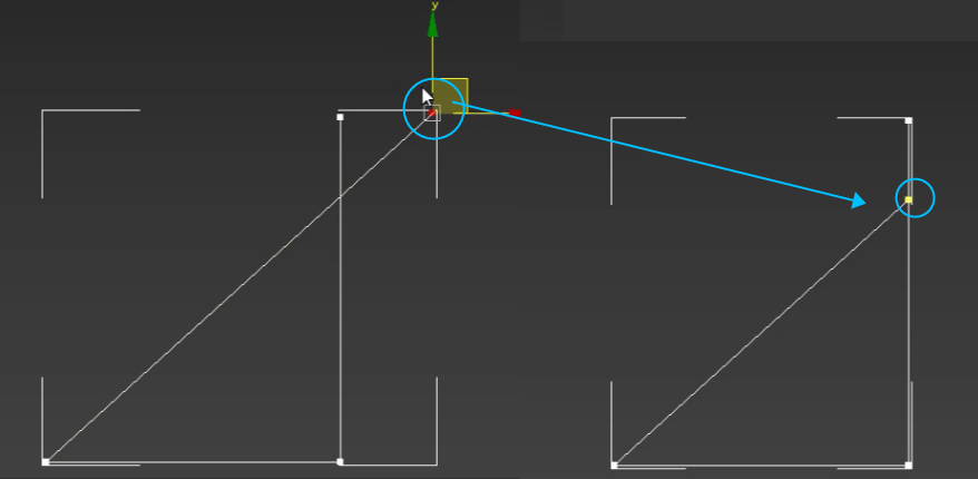
Merge: Select target vertices and click to merge within the shape;
Spline Intersection
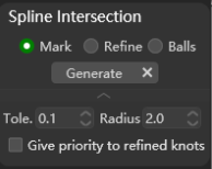
Supports adding markers or generating new vertex/sphere for intersecting splines in a shape.
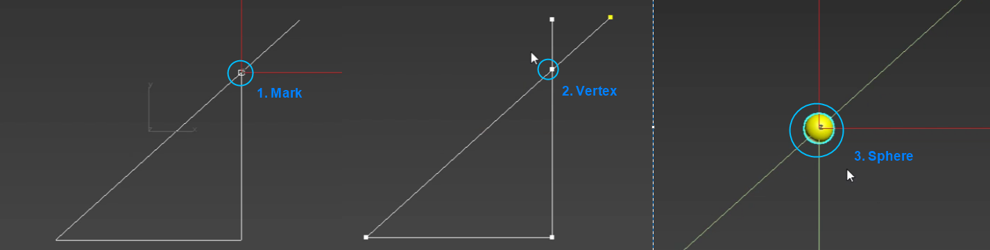
Mark: Select the shape, choose Mark and clickGenerateto add a mark on the intersection point, only for viewing, no actual function;+ Vertex: Select the shape, choose + Vertex and clickGenerateto add a new vertex on the intersection point;Sphere: Select the shape, choose Sphere and clickGenerateto add a sphere model on the intersection point;±: Tolerable offset range;Radius: Radius of the generated sphere;Precise positioning of vertices: Check to apply precise positioning of generated vertices, this may affect the shape;
Shape to Plane
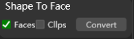
Supports converting a closed outer shape into a plane.
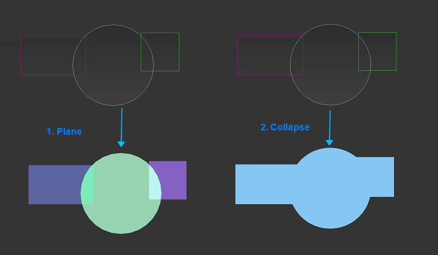
Plane: Check and clickConvertto convert the shape to a plane;Collapse:Check to and clickConvertto combine the stack operations of one or more selected objects into an editable shape, and perform a Boolean operation on them at the same time;
Extract Shape

Supports extracting shape outlines from target objects.
Offs.: After setting, the extracted shape will be offset along the surface normal direction of the target object according to the value;Extract: Click to apply extraction operation of the target object as a whole;- Extract
+: Click to apply extraction operation of the target object separately;
Note:
Please switch to plane selection in edit mode for target object extraction.
Extract Wireframe
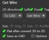
Supports extracting wireframe from target objects.
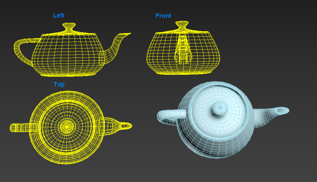
- Perspective: Check to extract object wireframe from
Leftview/Frontview/Topview; To CAD: Click to extract the target model according to the checked perspective in 2D and display it like CAD does;- To CAD
+: Click to extract all models according to the checked perspective in 2D and display it like CAD does;
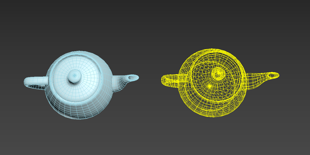
Get Wire: Click to extract the wireframe of the specified view of the target model;- Get Wire
+: Click to extract the wireframe of the specified view of all models in the scene;
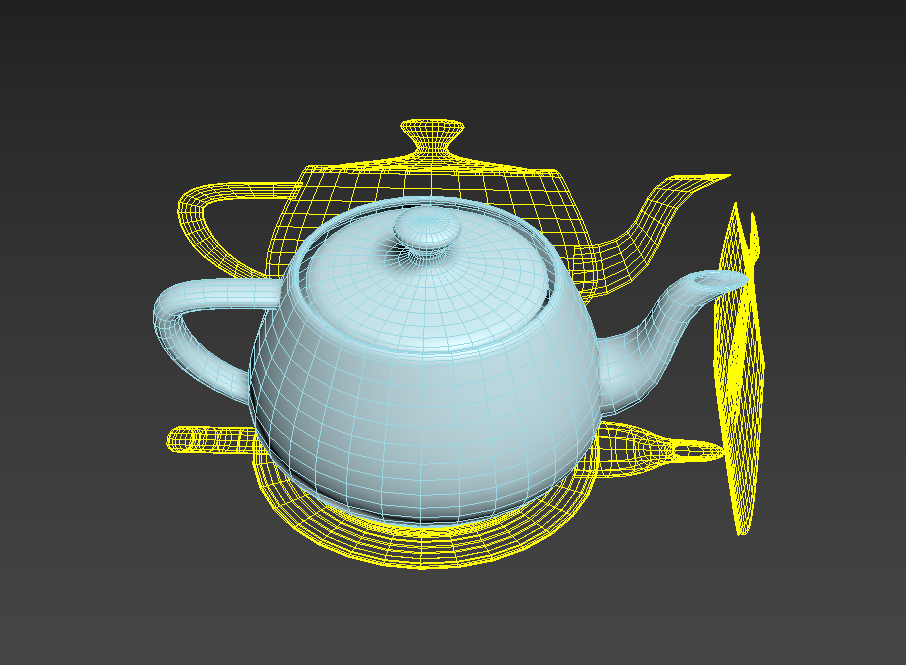
Projection perspective display: Check and click To CAD/ To CAD + to display the extracted 2D wireframe in the object projection perspective;Save as CAD: Click to export the extracted wireframe as a CAD file;
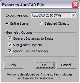
Options: Check to call out the “Export to AutoCAD File” window of 3ds Max when exporting the extracted wireframe as a CAD file;
Extract Sections
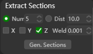
Supports extraction of specified shape of cross-sections of target objects based on set parameters.
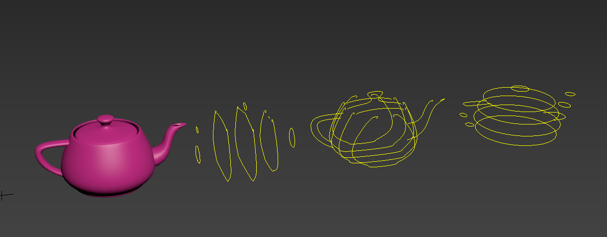
Num.: Select and set to extract the cross-sectional shape by quantity (divided into equal parts according to the size of the object);Dist.: Select and set to extract the cross-sectional shape by distance;Perspective: Check to extract the cross-sectional shape from X axis/Y axis/Z axis;Weld: Set the threshold for welding vertices. When two vertices are within this distance, they are welded for smoothing purposes;